No one wants to sail in a ship that can sink because of a single hull breach.
This led to the development of bulkheads, which are vertical partition walls that divide a ship’s interior into watertight compartments.
Cell-based architecture attempts to follow the same concept in software development.
In cell-based architecture, there are multiple isolated instances of a workload, where each instance is known as a cell. There are three properties of a cell:
Each cell is independent.
A cell does not share the state with other cells.
Each cell handles a subset of the overall traffic.
For example, imagine a web application that handles user requests. In a cell-based architecture, multiple cells of the same web application would be deployed, each serving a subset of the user requests. These cells are copies of the same application working together to distribute the workload.
This approach reduces the blast radius of impact. If a workload uses 5 cells to service 50 requests, a failure in only one cell means that 80% of the requests are unaffected by the failure.
In other words, failure isolation is the biggest benefit of a cell-based architecture.
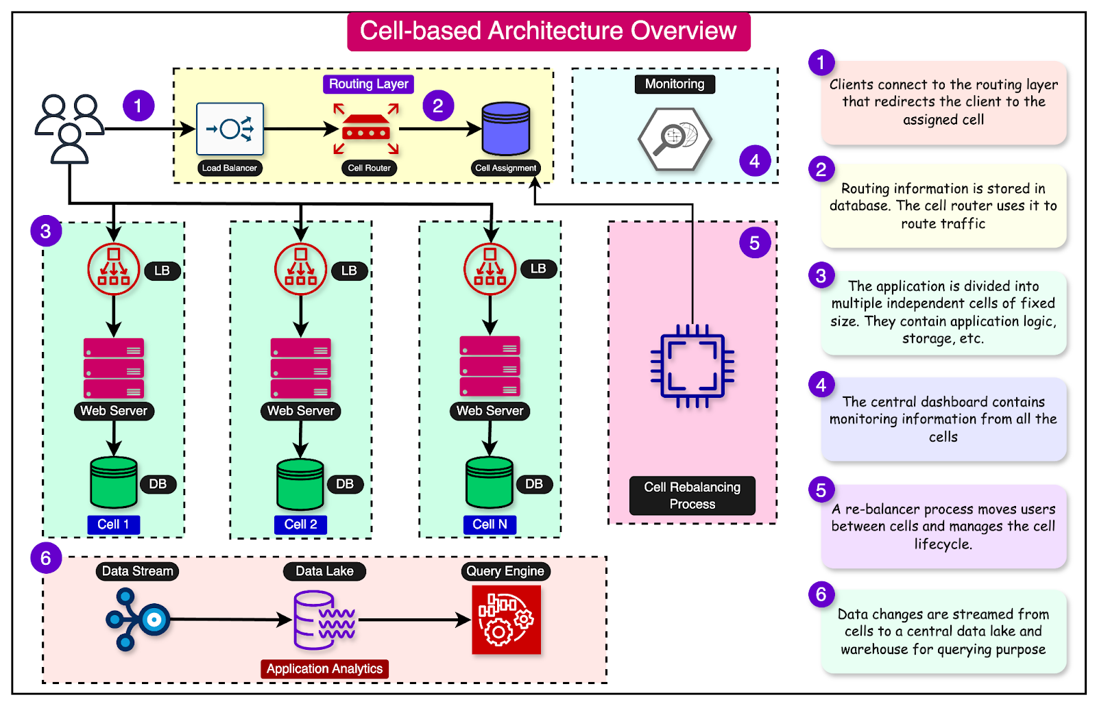
In this post, we will learn about the various aspects of cell-based architecture and its various components in more detail.
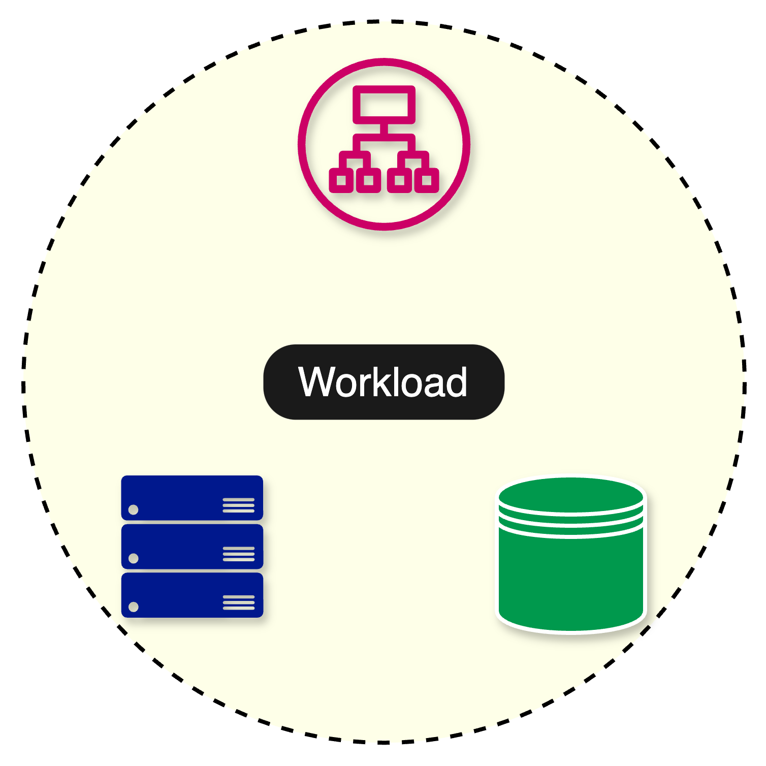
Before going further, let’s understand the concept of a workload.
A workload refers to the amount of work that is assigned to a particular system. It represents the computational tasks, processes, or applications that consume CPU, memory, storage, and network bandwidth resources.
We can define the workload of an application using several metrics.
One common metric is requests per second (RPS), which measures the number of requests an application processes per second. For example, a popular e-commerce website handles an average of 5000 requests per second.
The diagram below shows an application divided into three layers: a load balancer, a web server, and a database. The application serves the entire workload of 5000 requests per second. Any failure impacts 100% of the requests.
The impact of failures changes significantly with the adoption of a cell-based architecture.
In a cell-based architecture, the workload is divided across multiple cells. This means that if one cell fails or becomes overloaded, the other cells can continue to serve requests, minimizing the overall impact on the system.
At a high level, a cell-based architecture has three main parts:
Cell router: This is the thinnest possible layer with the sole responsibility of routing requests to the right cell.
Cell: A complete workload with everything needed to operate independently. A cell can contain application services, load balancers, and databases. The components within a cell communicate with each other through appropriate network channels.
Control Plane: The control plane takes care of administration tasks such as provisioning new cells, de-provisioning cells, and migrating cell customers.
Let’s compare cell-based architecture with other architectural patterns, such as monolithic and microservices.
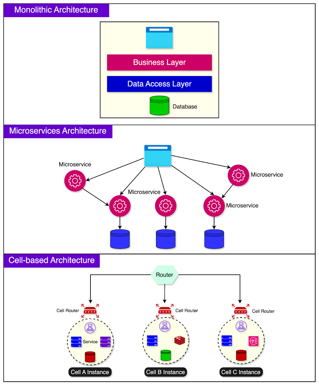
In a monolithic architecture, the entire application is built as a single, tightly coupled unit. It’s like having a giant building that houses all the government functions needed to run a city.
Monolithic applications are easier to develop initially but can become harder to maintain and scale over time.
Microservices architecture breaks down the application into smaller, independent services where each service has its codebase and can be deployed separately.
This is similar to having a separate specialized building for each function in the city. One downside is that the communication between services can become complex, and managing multiple services can be challenging.
Cell-based architecture tries to find a balance between monolithic and microservices architectures.
In this approach, related functionalities are grouped into a cell. A cell can comprise multiple components necessary for its functionality, including infrastructure pieces like load balancers.
The goal is to make each cell as self-sufficient as possible, with minimal external dependencies. This allows for efficient workload distribution across the cells.
Each cell can be developed, tested, deployed, and scaled independently.
Certain types of workloads are ideally suited for cell-based architecture:
Applications where downtime has a huge negative impact on customers.
Companies that are going through a hypergrowth phase with growth rates over 40%.
Stringent Recovery Point Objective (RPO) and Recovery Time Objective (RTO) goals.
Multi-tenant systems where some tenants require dedicated infrastructure.
Let's explore the details of implementing a cell-based architecture.
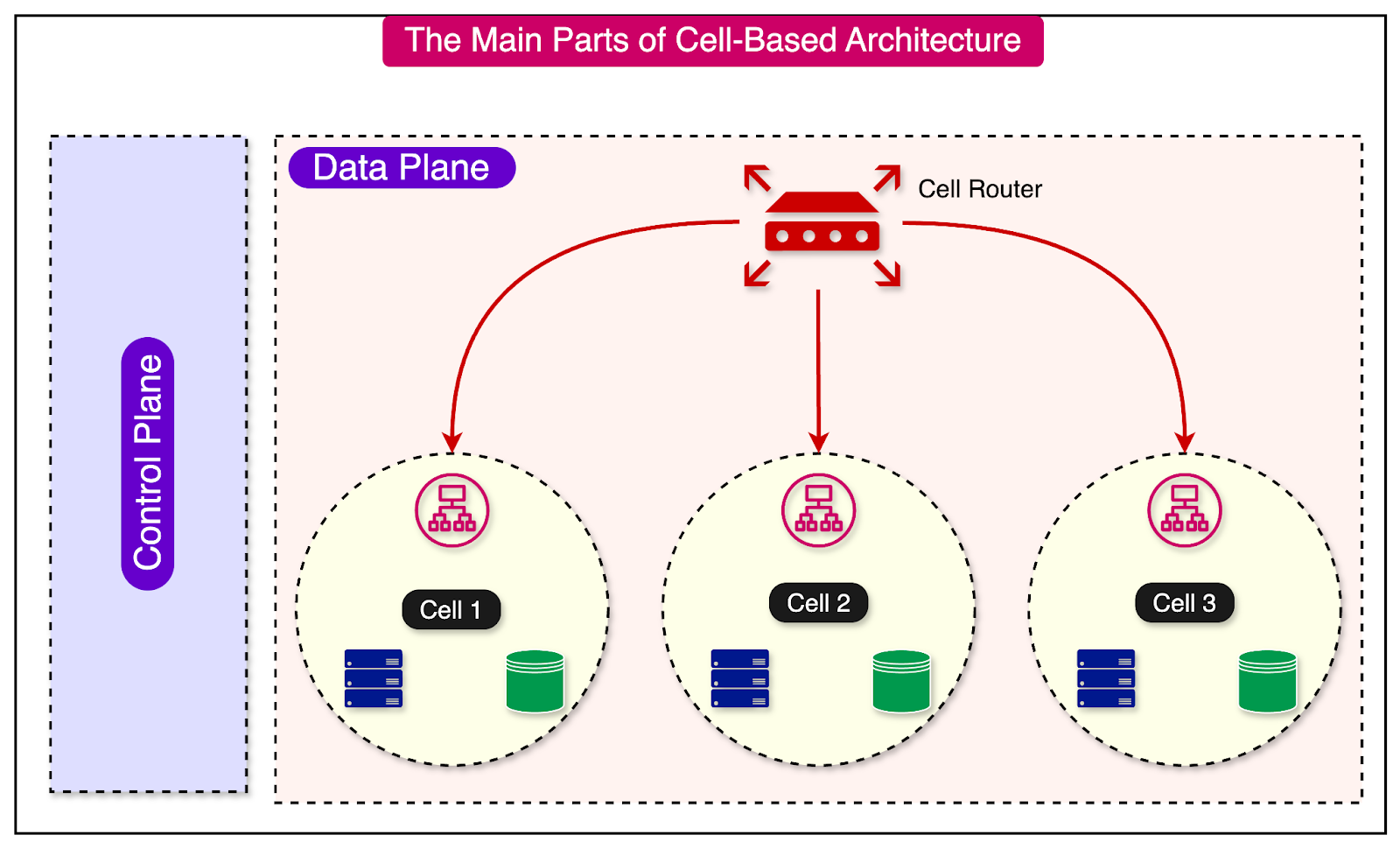
Two networking concepts play a key role in cell-based architecture - the control plane and the data plane.
In the context of cell-based architecture, control planes are meant for administrative tasks such as provisioning, migrating, and monitoring cells. The data plane supports the primary function of the service.
For example, if you have 10 cells serving traffic and the number of users goes up, the control plane provisions a new cell and propagates the information to the cell router so that it knows where the requests should be sent.
The router and the cell (part of the data plane) execute the work based on the direction provided by the control plane.
A cell is an instance of the complete application workload. It has everything needed to operate independently.
Ideally, a cell should be completely independent and not share its state with other cells. It should be unaware of the existence of other cells. This is because dependencies between cells can eliminate the benefits of a cell-based architecture.
For example, an application can consist of a load balancer, service instances, and a database for proper functioning. These components together form a cell. Another cell instance will contain copies of these three components.
One common way to divide your workload in a typical cloud-native environment is to distribute the cells across multiple availability zones.
The diagram below shows this approach:
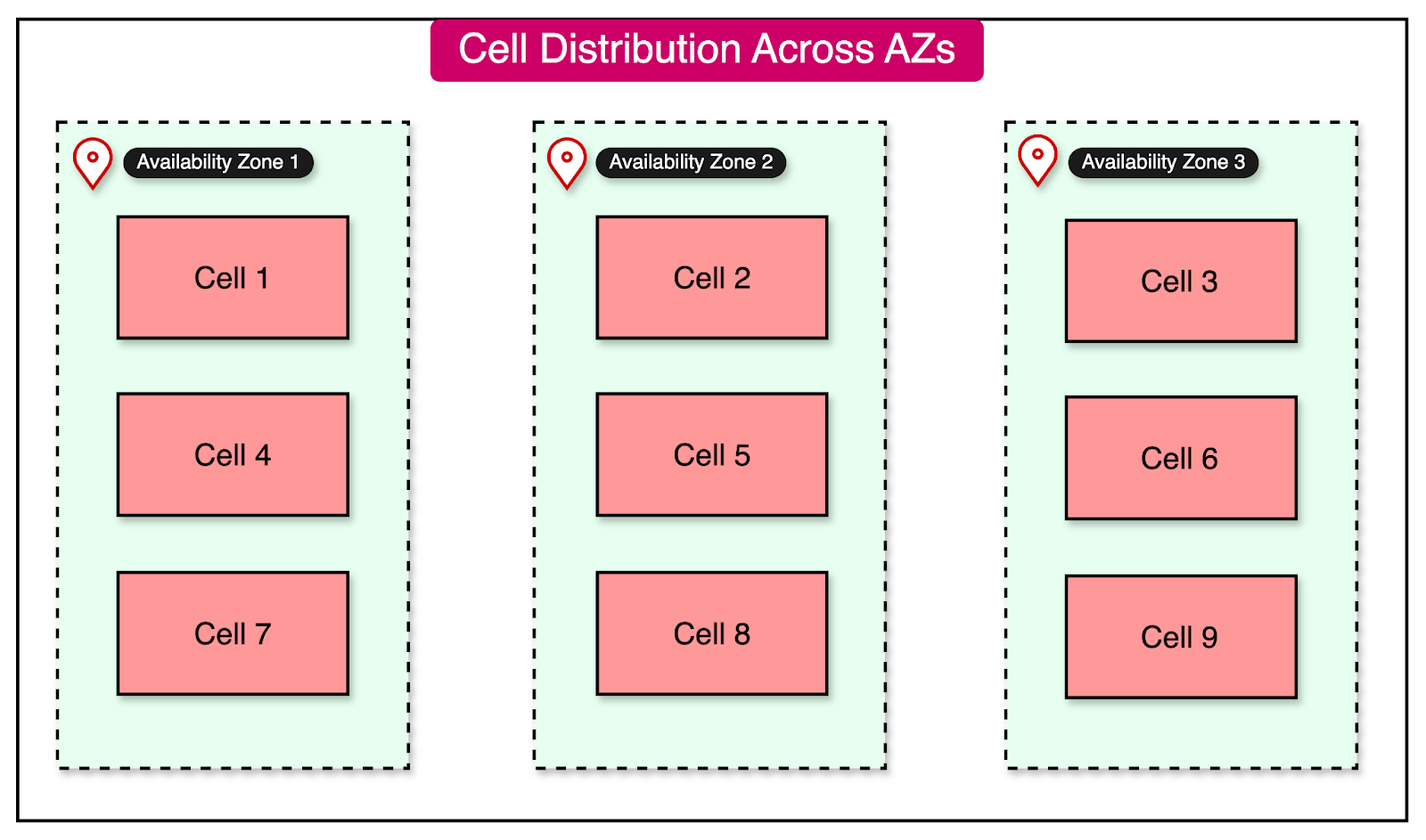
The advantage of this approach is that a failure in one availability zone doesn’t impact the workload in other zones. Also, it is possible to drain the traffic from a failing availability zone to a healthy one when needed.
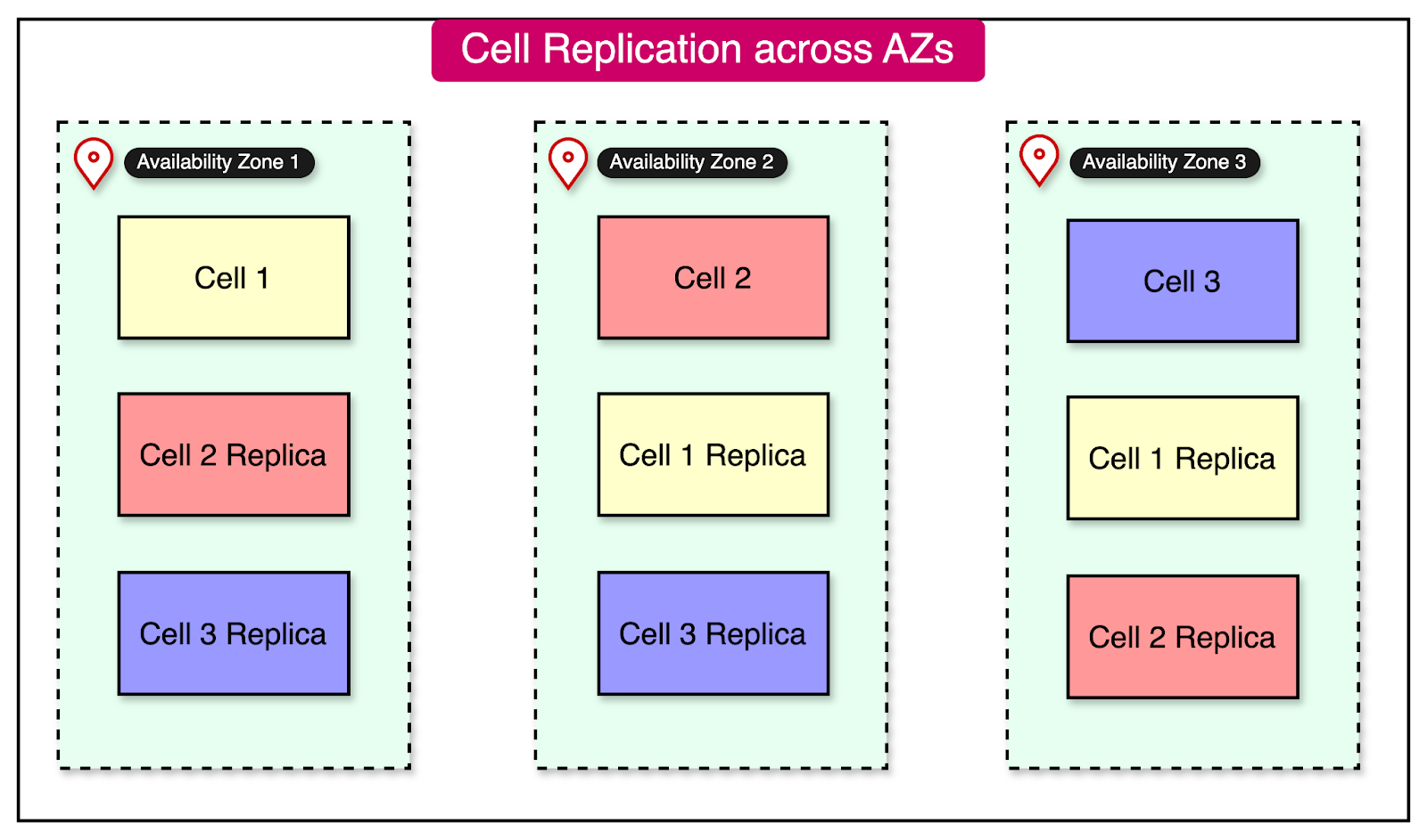
On the downside, the state of a cell has to be replicated across multiple cells in different availability zones. See the diagram below:
Partitioning traffic between cells is one of the most important aspects of a cell-based architecture.
This division is performed using a partition key, which can be simple or composite. Ideally, the key should be chosen based on how the workload is distributed. It should result in minimal cross-cell interaction.
For example, UserId is a common partition key for many use cases, such as a social networking site. However, if certain users are extremely popular and attract a lot of traffic, we may have to allocate multiple cells to them.
Alternatively, it might be better to introduce a second dimension in the partition key, such as the PostType. The PostType dimension could represent different types of posts, such as text, image, video, and so on, resulting in a more uniform traffic partition. Ultimately, this decision is based on the application design.
Above all else, scatter-gather interactions where the partition key results in calls to multiple cells should be avoided or minimized.
Let’s look at a few important partitioning algorithms that can be used to map keys to cells.
In this approach, we explicitly map every key to a particular cell.
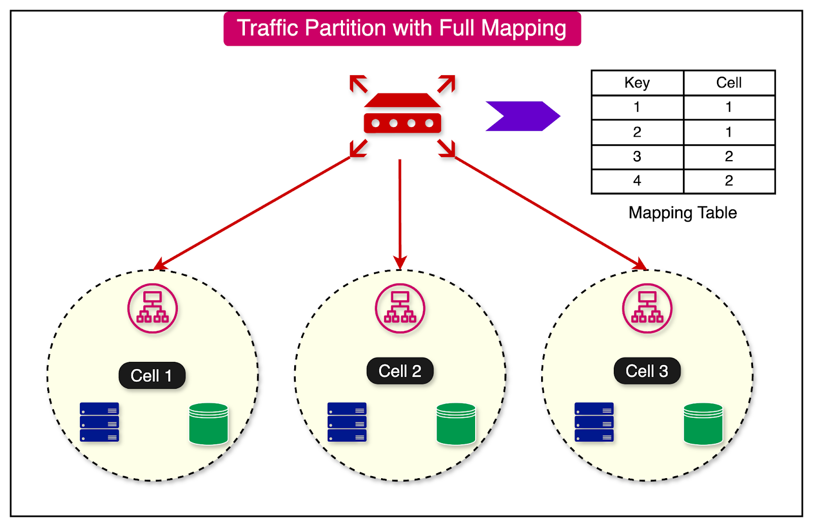
While this approach is simple to implement and gives a lot of control over the distribution of keys, there are a few major downsides:
There is a critical dependency on the mapping table.
A large amount of state has to be stored.
The range-based mapping maps ranges of keys to cells.
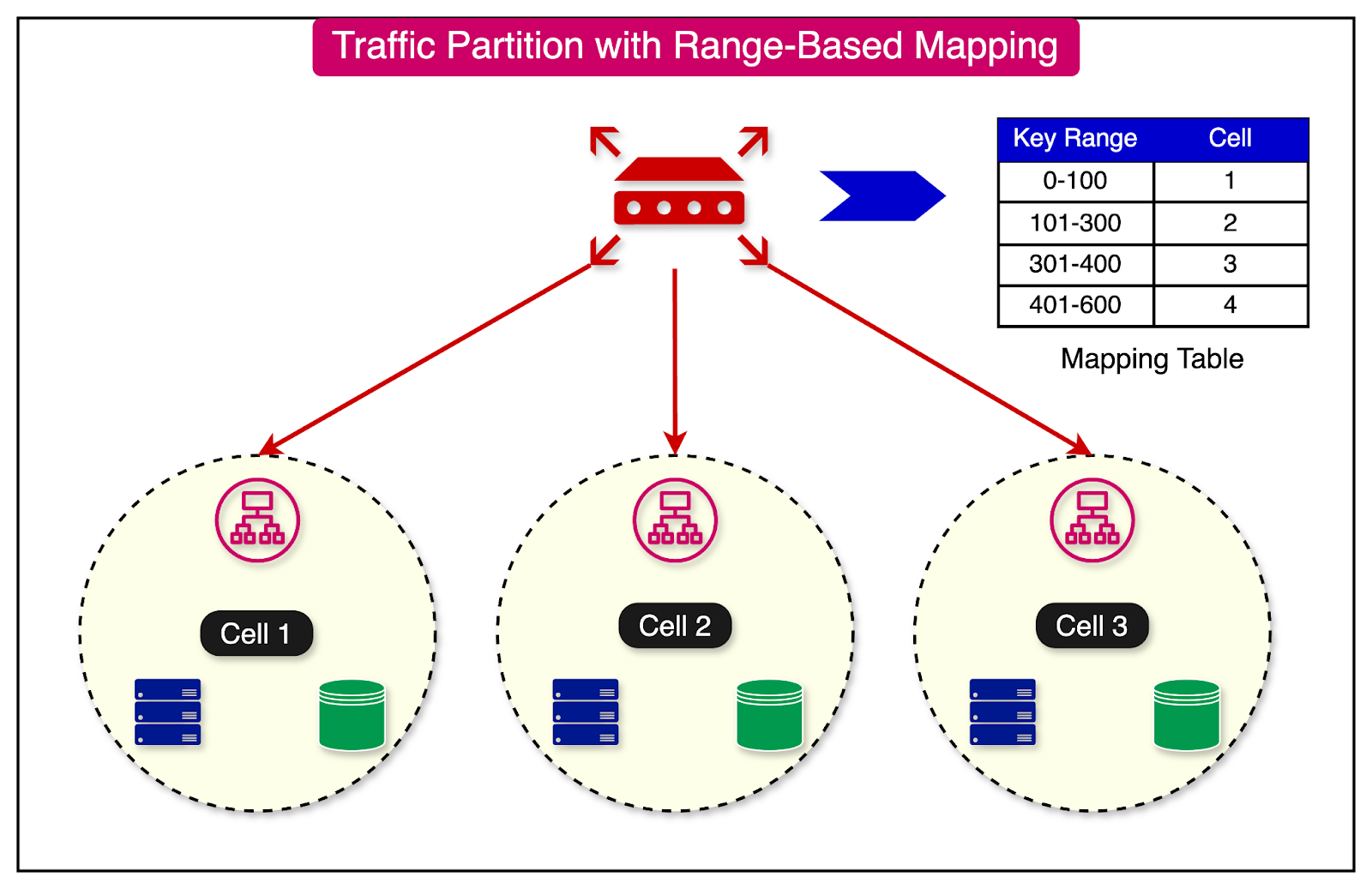
The advantage of this approach is that it reduces the performance issue of full mapping by grouping keys.
However, on the downside, it can also result in hot cells if specific keys within a particular range have a large amount of traffic.
A third approach to partition traffic is consistent hashing.
In this approach, we configure a large number of logical buckets mapped to a small number of physical cells.
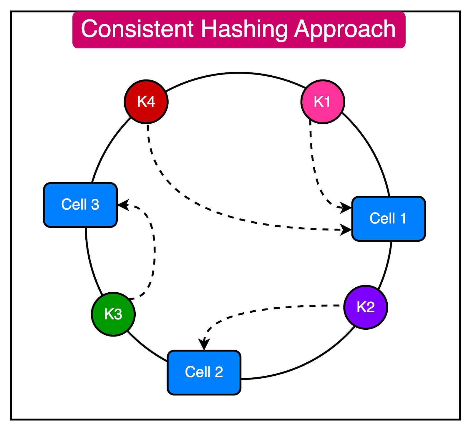
Going from a key to a cell is a two-step process:
Map the key to a logical bucket using the modulo approach.
Locate the cell for that bucket using a cell mapping table.
The advantage of this approach is that changing the number of cells does not require rebalancing all cells. However, there is a chance of uneven distribution across the cells.
The cell router is a shared component between cells. It does not belong to a specific cell and exists on top of all the other cells.
This thin layer should not contain any complex business logic and must remain as simple and horizontally scalable as possible.
We can use multiple approaches to perform cell routing:
Routing with DNS
Routing with API Gateway
Special router application with in-memory cell mapping
Async cell router with in-memory cell mapping (for non-HTTP requests)
The diagram below shows these approaches in more detail:
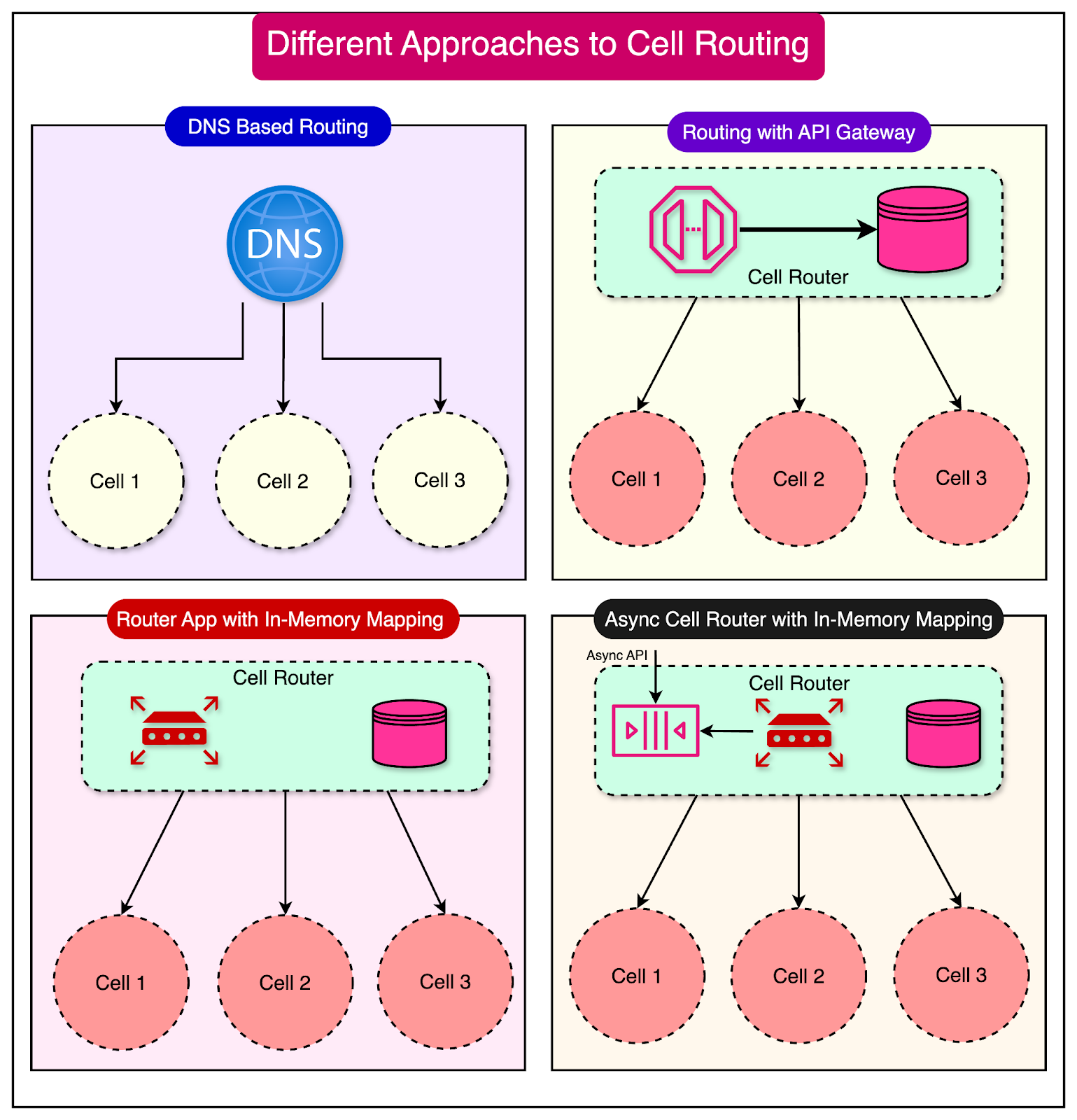
Whatever the approach, a cell router's main dependency is access to each partition key's mapping state. The mapping state can be pre-configured, stored in a database/cache, or stored in memory with the router process.
One question comes up at this point about the resilience of the cell router.
Considering that the cell router stores the shared state of all cells, it can become a single point of failure. Therefore, building the cell router with maximum reliability and scalability is important.
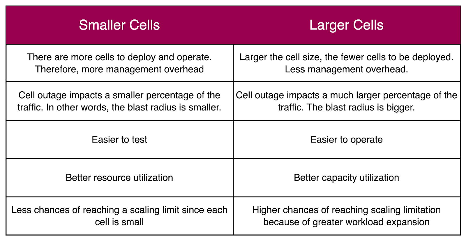
The maximum size of a cell is an important consideration in a cell-based architecture. It is a good idea to use a consistent cell size across availability zones.
The trade-off is whether to choose small or large cells. Here’s a table that compares smaller cells with larger cells.
Cell placement is another responsibility of the control plane. It involves two main aspects:
Onboarding new tenants and customers
Creation of new cells
There are several data points needed for making these decisions:
Total capacity of each cell and used capacity
Utilization percentage of a tenant or customer
Quotas and limits for each cell.
Allocation, scheduling, and forecasting are key competencies for efficient cell placement. For example, when a customer utilizes more resources in a cell, we need to migrate them to other cells. Sometimes, a customer's workload becomes too big and requires a dedicated cell.
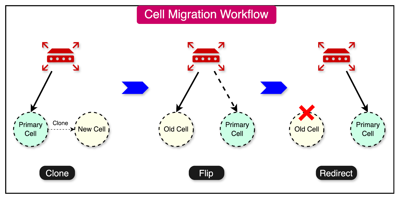
A typical cell migration process goes through the following phases:
Clone the data from the current location into the new location. The new location is not an authoritative copy.
Change the new location copy to act as the authoritative copy.
Redirect traffic from the old location to the new location.
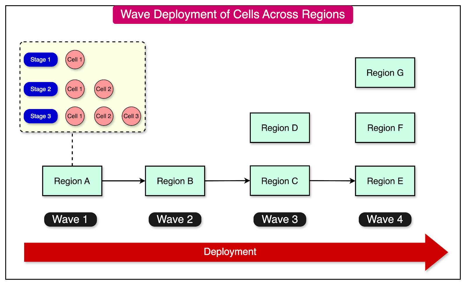
Using a cell-based architecture, we have multiple instances of the workload to deploy and operate. This makes cell deployments challenging compared to deploying a single workload instance.
It is essential to have an automated CI/CD pipeline.
To make the process less risky, a deployment must also be tested on an individual cell before being rolled out to other cells.
A good approach is to carry out the deployment in waves. With each wave, we should monitor the metrics and roll back the deployment in case of a failure.
Let's now examine a couple of real-world case studies to better understand the practicalities of cell-based architecture.
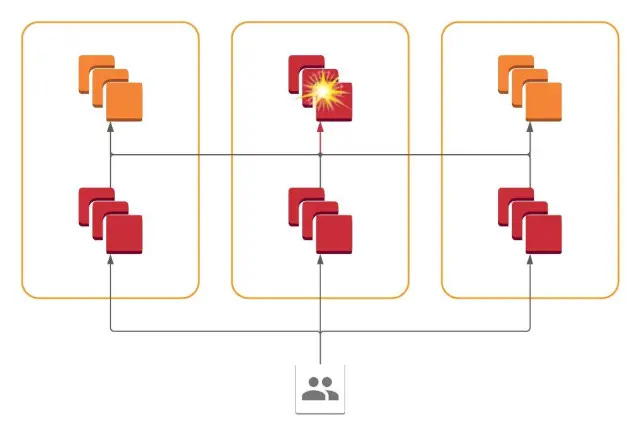
In 2021, Slack faced an incident where its cloud provider experienced a network disruption due to a failing network link in one of the availability zones.
Even though Slack operated a global, multi-regional network, the outage in a single availability zone was visible to the users. This was something they had not expected, and it was a poor user experience.
Upon investigation, they realized that certain API requests from users could fan out into hundreds of RPC calls to service backends, which were spread across AZs. Any errors in one AZ could appear in frontend applications in all AZs.
This is shown in the diagram below:
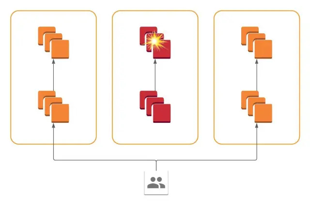
To solve this, Slack implemented a cellular architecture where all services are present in all availability zones, and each service only communicates with services within its availability zone.
In other words, failure of a system within one AZ is contained and restricted to that AZ. This allows the operator to drain traffic from the problematic AZ and reduce the blast radius of the impact.
DoorDash started as a monolithic application. However, they evolved to an architecture based on microservices and cell-based design.
As part of this approach, all microservice pods are deployed in multiple isolated cells, with each service having one Kubernetes deployment per cell. Singleton services or yet-to-be-migrated services are deployed in a global cell.
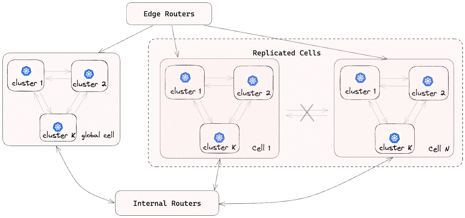
To ensure isolation between cells, no inter-cell traffic is allowed. This helps reduce the impact of a single-cell failure.
Based on what we’ve discussed about cell-based architecture, here are a few best practices while designing such a system:
To support a gradual transition, introduce a cell router layer on top of the existing stack. Add more cells over time and let the router layer take care of directing the traffic.
Conduct a failure mode analysis to assess the resilience of each cell. This involves identifying failure points, scenarios, and necessary measures for the cells to recover from the failures gracefully.
Cell boundaries should ideally align with the bounded context. This is good for team autonomy and clear ownership.
Design the cells to scale independently based on their specific requirements and traffic patterns.
Eliminate or minimize dependencies between cells to maximize the benefits of a cell-based architecture. Avoid shared resources like databases across cells to prevent the introduction of a global state.
Formulate a cell migration strategy from day one in case a customer quickly becomes too big for a cell.
Create a wave-based deployment strategy for the cells to mitigate the impact of problematic changes.
In this post, we’ve looked at cell-based architecture in detail.
It is a relatively modern architectural approach that aims to address the challenges of scalability, fault tolerance, and maintainability in complex systems that are going through the hypergrowth phase or belong to the mission-critical category.
Some key takeaways are as follows:
Cell-based architecture focuses on breaking down complex systems into smaller, independently deployable units known as cells.
Cells encapsulate specific workloads and have minimal dependency outside their boundaries.
The core components of cell-based architecture include cells, traffic partitioning, cell routing, and control planes.
Implementing cell-based architecture requires best practices like failure mode analysis, defining clear boundaries, minimizing dependencies, and avoiding shared resources.
Real-world case studies of Slack and DoorDash demonstrate the successful adoption of cell-based architecture in the industry.